All You Need To Know About Brushless Motor Sensor
- joddiemarshall6
- Sep 19, 2022
- 3 min read
To control the speed of a brushless motor, an angular position sensor is needed. There are several ways of doing this, including the use of Hall effect sensors and an Observer. These methods are discussed in this article. You will also learn about PWM schemes and how to adjust the Stator resistance.
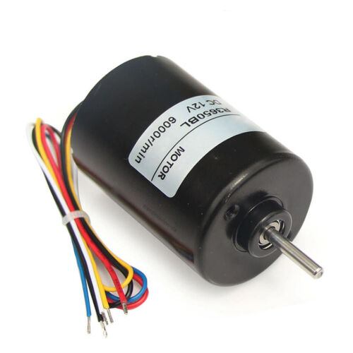
Hall Effect Sensors
Brushless Motor Sensors rely on Hall effect sensors to regulate motor speed. These sensors have several advantages. Hall sensors can be used as indexes in a software lookup table. The table can provide information on phase driving based on the rotor's current position. This can help prevent damage to the motor.
Hall effect sensors can be highly sensitive and stable. They are also resistant to dust, vibration, and water. These properties make them an excellent choice for use in automotive systems. They can also be used to detect position, speed, and distance. Hall effect sensors can be sealed, which helps them avoid corrosion and moisture.
Hall effect sensors are often used in industrial settings. They are used in many linear sensing applications, including robotics, conveyor systems, and rotary encoding. They are also used as proximity sensors and safety switches.

Observer Brushless Motor Sensor
The Observer brushless motor sensor is designed to monitor the health of a brushless direct-current motor. It is small and can be integrated into places that other sensors can't. The sensor is also designed to be robust and resistant to high temperatures and pressures. It is ideal for monitoring motor health because it prevents serious motor failures and improves the reliability of the control system.
The Observer brushless motor sensor can be used for a variety of applications. Its low-cost, high-precision performance makes it suitable for use in applications that require high dynamic performance. Its sinusoidal commutation feature helps reduce noise. It is available in high-frequency and low-speed versions. Its design and software are tailored to the specific drive system.
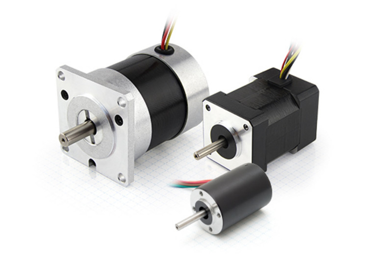
PWM Scheme
A PWM scheme is used to control a brushless motor sensor. The PWM scheme applies a positive a-phase voltage to the motor by pulse width modulating both Sa and Sb. This is followed by a negative a-phase voltage, which is applied by reversely applying the bus voltage to Sa and Sb.
The floating phase voltage is equal to half of the DC rail voltage, and the end of the PWM on-state is chosen as the zero-crossing detection point. The sampling of the signal is noise-free and accurate. The PWM scheme for the brushless motor sensors can be implemented for different speeds, depending on the purpose.
PWM control schemes are the most common control schemes for high-speed applications. The PWM switching cannot be performed independently of inverter commutation, so there must be some delay. In a perfect world, the commutation instant will occur at the end of a PWM period. In practice, this delay leads to an undesirable delay.
Stator Resistance Adaptation
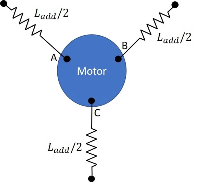
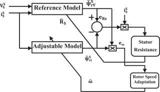
Stator resistance adaptation is a key process for achieving optimal performance of speed sensorless systems in low-speed ranges. It has a wide range of applications and is relatively easy to implement. In this paper, we will discuss two of the most promising methods for achieving this. The first one is the use of the Lyapunov stability criterion.
Another method uses the response peak value of the stator winding current. This method can detect rotor position by using the current that passes through the stator windings. It uses the same principle as that used for magnetic sensors but is simpler.
Observer Cable
A brushless motor sensor is not the only way to monitor the performance of a motor. It is also important to monitor the overall health of a motor to avoid severe failures and improve the reliability of the control system. One common way to monitor the motor is through an observer cable. This cable transmits the signal from the motor controller to the motor.
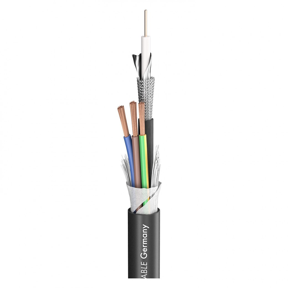
Using an observer cable allows you to monitor the mechanical load on a brushless motor. This is extremely useful for analysing the behaviour of a motor when under varying loads. It can help calculate the mechanical load imposed on a motor, and it makes the process of controlling the motor simpler and more precise.


Comments